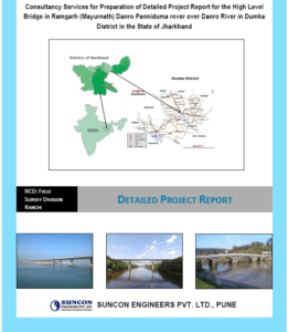
Road Construction Department (RCD), Government of Jharkhand in order to explore the necessity and feasibility of providing High Level Bridges in 3rd km. of Tatanagar Railway Station to Baroda Ghat Road under RCD, Road Division, Jamshedpur in East Singhbhum District in the state of Jharkhand for better connectivity, catering future traffic, efficient commercial transportation, traffic decongestion.
Topographical Survey –
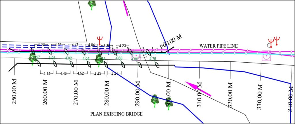
As per our topographical survey the site plan and site conditions are given below:
The 4 boreholes are taken at the site of work (two on upstream side & two on downstream side). From the exploratory bore holes at the site it is observed that sub soil formation at this site consists of cohesion less soil at surface layer. Refusal strata observed at the depth of 3.0 to 6.0m. And fractured to fresh rock observed at the depth.
As per the reconnaissance survey there are various utilities belonging to railway authority on existing bridge. The Railway authority had insisted to not to disturb their utilities. There is also number of structures along the alignment of bridge. In ordered to not to disturb existing utilities and structures, it is proposed to construct 10 spans of 6m. RCC box culvert 5.5 m. on upstream side. It is also proposed to divert existing course of Nallah as shown in drawing.
Sub Surface Exploration Report –
The 4 boreholes are taken at the site of work (two on upstream side & two on downstream side). From the exploratory bore holes at the site it is observed that sub soil formation at this site consists of cohesion less soil at surface layer. Refusal strata observed at the depth of 3.0 to 6.0m. And fractured to fresh rock observed at the depth
Present Proposal:
We have studied 2 options for construction of bridge based upon the hydraulic survey details and Geotechnical investigations. The details are as below.
Option no. 1 – The RCC Bridge is proposed over existing bridge.
The 12 span of 8 m are proposed with construction of 1200 mm dia. monopiles on either side of bridge at the interval of 8 m. The integral bent cap with 24 m. module is proposed, so that there will be sleek section & height of approaches at Bridge section will be minimum. This section is proposed over existing bridge & then single pier & solid slab is proposed, so that it will be economical. The width of bridge is proposed 11.50 m, as per IRC SP:73-2018.
In this case it is necessary to shift utility as well as dismantle existing structure, along the approaches of bridge.
As per the reconnaissance survey there are various utilities belonging to railway authority on existing bridge. The Railway authority had insisted to not to disturb their utilities. There is also number of structures along the alignment of bridge. In ordered to not to disturb existing utilities and structures, it is proposed to construct 10 spans of 6m. RCC box culvert 5.5 m. on upstream side. It is also proposed to divert existing course of Nallah as shown in drawing.
Loadings – One lane of class 70-R and one lane of IRC Class-A or three lanes of Class-A loading on carriageway has been considered. After various combinations and static positioning of Live Loads it was found that one lane of 70-R+one lane of Class-A loading produces the severest condition and accordingly same has been taken for design of foundation and substructure.
Foundations and Substructure – As per sub surface exploration report, weathered rock stratum with sufficient bearing capacity is available at shallow depth; hence open foundation has been proposed and designed for the box culvert. All structures are proposed in M-30 Grade concrete.
Crash Barrier – RCC Crash Barrier in M-30 Grade concrete as per MORT&H standard has been provided.
Wearing Coat – 75 mm thick RCC wearing coat with M-30 Grade concrete as per IRC/ MORT&H standard is being proposed with overlay of 25mm mastic asphalt.
Approach Slab – 3.5 m long and 300 mm thick RCC approach slab in M-30 Grade concrete is being proposed at either end of bridge with one end supported on dirt wall and other end resting on soil. 150 mm thick leveling course in M-15 concrete Grade has also been proposed under the approach slab.
Drainage spouts – Drainage spouts are proposed as per MORT&H standard plans.
Specifications: MORT&H specifications for Road and Bridge works, 2013 (Fifth Revision) should be followed for execution of works unless otherwise specified. The relevant IS codes for various types of tests and testing procedures should be followed.
Drawings: Based on the design of various components of the bridges, GAD for the designed structure has been prepared.
GEOTECHNICAL INVESTIGATION
In an attempt to facilitate the design of the proposed new construction of the foundation structure of the DETAILED PROJECT REPORT OF HIGH LEVEL BRIDGE, IN 3RD KM OF TATANAGAR RAILWAY STATION TO BARODA GHAT ROAD UNDER EAST SINGHBHUM DISTRICT IN THE STATE OF JHARKHAND.
A subsoil investigation work was programmed and executed. The scope of the soil investigation consisted of making four of bore holes at this site.
The formation at the site is to be reported for various layers presented at their respective depth along with their thickness. This would also include the subsoil properties for each stratum so as to come up with the design parameters for designing foundations, the depth of foundation and the selection of type of As the ground water table location influences the bearing capacity of a foundation and the method of construction of a foundation at the site, its location has also to be found. Soil samples both in disturbed and undisturbed condition wherever possible are to be collected. These samples would be different laboratory tests to obtain various properties of sub-soil formation. The exploration of the sub-soil formation being limited to four nos. bore holes it is suggested that due weighted is given to the unexplored part of the area at the time of selecting design parameters
The fieldwork consisted of four nos. of bore hole at pre-determined location. The detail of fieldwork like depth of bore hole, date of the field work of site are presented below in tabular form
| Bore Hole / Test No. | Depth of Bore Hole (m) | Date of Commencement | Date of Completion |
| BH – A1 | 13.50 | 09/11/2020 | 11/11/2020 |
| BH – P5 | 17.00 | 17/11/2020 | 18/11/2020 |
| BH – P8 | 17.00 | 05/11/2020 | 07/11/2020 |
| BH – A2 | 12.00 | 07/11/2020 | 09/11/2020 |
The fieldwork also included collection of disturbed and undisturbed soil samples and conducting standard penetration tests at regular intervals.
The bore holes of 150mm diameter (SX size) are initially sunk by hand auger boring upto the water table and thereafter by rotary boring with bentonite mud circulation.
In case rock encountered, bore holes of 150mm diameter (SX size) are initially sunk by hand auger boring upto the refusal strata (N>100) in line with specification. For further advancement of bore holes rotary drilling technique is adopted upto the termination depth as directed by the client. Drilling was done with standard G.O. type rotary drilling machine as per IS: 6926. In this method the hole was advanced by rotating a system, consisting of a series of hollow drill rods to the bottom of which is attached a barrel with a TC/Diamond coring bit, by means of a diesel operated engine.
When the rod with the coring bit is rotated, downward pressure is applied into the bottom of the hole through the hollow drill rods. Water comes up through the annular space between the drill rods and the bore hole and is collected in the water sump, from where it is re- circulated. Water services the dual function of cooling the bit as it enters the hole and carrying cutting from the bottom of the hole on its return journey to the surface.
Ground water level in the bore holes within the explored depth below the existing ground level was observed during boring work and also after 24 hours of the completion of the field work.
SOIL PROFILE AND RECOMMENDATION:
From the exploratory bore holes at the site it is observed that sub soil formation at this site consists of cohesionless soil at surface layer. Refusal strata oserved at the depth of 3.0 to 6.0m. And fractured to fresh rock observed at the depth of 9.0m to 14.0m. Details of the formations along with the ìNî values are shown in the field bore log data sheets.