PROJECT DETAILS:
Recently MIDC has developed Butibori Industrial area Phase-II, on about 278 Hect. of land adjacent to existing area. All the infrastructure facilities like asphalted roads, distribution pipelines, ESR of 500m3 capacity, street lights etc. are provided in this Phase-II area. The plots allotment is in progress and construction activity of some units have been started. Hence it is necessary to provide the effluent collection & conveyance system to cater the demand in near future as prospective industries likely to come in this area.
In view of this MIDC has appointed Suncon Engineers Pvt. Ltd for the preparation of detailed project report on providing the effluent drainage system in Butibori Phase-II area.
Preliminary Investigation:
The Engineering survey has been carried out for the proper planning and design of effluent collection system. Following surveys have been carried out:
Topographical Surveys – The basic objective of the topographic survey was to collect the essential ground features of nala, roads, utilities etc. The data collected will result in the final design for effluent drainage system in Phase II area and is also used for the computation of earthwork and other quantities required.
Detailed Survey of Topographical Features –
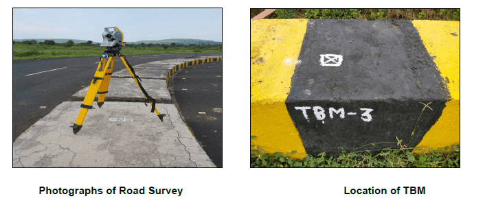
Topographic survey is carried out using Total Station of 1-sec accuracy for detailed mapping and traversing. As part of the survey, the following activities were carried out
(i) Installation of Bench Mark: As first step of the survey, Temporary Bench marks of 5 Nos are fixed on Permanent structure at various locations. Details are given below.
(ii) The detailed cross-sections have been taken for full land width of roads at 20m interval for road length of 9.2Km.
(iii) The contour survey has been conducted with taking levels at 10m grid. The map is enclosed below.
(iv) Survey of Nala is also carried out having total length 4.2Km.
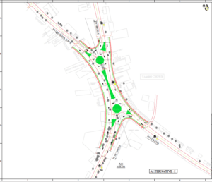
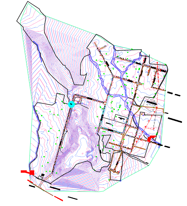
Contour Map –
The detailed contour map of Phase II area is prepared and is as below. It is seen that there is lowest point on south west side having RL 282m and lowest point on east side having RL 284m.
There is ridge in between above two points having maximum RL 301m. The general slope of area is towards south west side and east side of phase II area.
DESIGN CRITERIA:
The Water supply Scheme in Phase-II area is designed to feed water at the rate of 15cum/ha/day. As per guide lines given in the CPHEEO manual of Sewerage & Sewage treatment system November 2013 edition, 80% of demand is considered as finding its way to the effluent system and 5% is considered for Infiltration.
Design Period: – The Effluent collection system will be designed for 30 years period. The pumping machinery & effluent treatment plant will design for 15 years period, as per table 2.1 of manual of Sewerage & Sewage treatment system November 2013 edition. The rising main will be designed for Ultimate Stage requirement & the economical diameter is worked as per consideration of velocity, for lean flow, average flow & peak flow.
Peak Factor: – We have considered peak factor 3 as recommended by CPHEEO manual of Sewerage & Sewage treatment system November 2013 edition.
Effluent Collection Zones: –
Considering the topography of the area & the general slope pattern of drainage area we have proposed 2 Zone in Phase-II area. The Zone-I is on South-West side, Zone-II is on East side of Phase-II Area.
Hydraulics of Effluent: –
a) Flow – Friction formula: – Manning’s formula for circular conduits will be used for design of sewers.
V = (1/n) (3.968 x 10⁻³) D2/3 S1/2
Where
Q = Discharge in L/S
S = Slope of hydraulic gradient
D = Internal dia. of pipeline in mm.
R = Hydraulic radius in m.
V = Velocity in m/s
n = Manning’s coefficient of roughness as in Table 3-11
As HDPE/ Spun concrete pipes with socket spigot joints are proposed to be used, n value of 0.010 & 0.015 will be adopted respectively in the formula.
b) Velocity: – Minimum Velocity of 0.60m/sec. and Maximum Velocity of 3.0m/sec. Will be attempted as far as possible for Ultimate Stage flow.
c) Minimum diameter: – The adopted minimum dia. of sewer will be 150 mm irrespective of flow quantity.
d) Sewer transition: – Transition from smaller diameter to larger diameter is done by keeping the crowns of both sewer lines at same level i.e. by providing drop in manhole equal to difference in diameters.
e) Drop Manholes: – Drops up to 0.60 m. will be proposed to be accommodated within the manholes whereas drops of more than 0.60 m. are proposed to be accommodated by needful drop arrangement.
f) Depth of flow in Sewer: – The maximum depth of flow in the effluent collection pipe line will be restricted to 0.80 of dia. of effluent & there by the q/Q ratio is restricted to 0.97.
Manholes: –
Maximum Spacing of manholes is restricted to 30.0 m. Minimum depth of manholes is kept as 1.0 m. The inside diameter of manholes is kept as 1.40 m with 230 mm thick B.B. masonry for depth upto 1.50 m. and 350 mm thick B.B. masonry for depth more than 1.5 m. including 600 mm internal diameter RCC precast cover 100 mm thick. All manholes are proposed circular in plan & conical in shape with B.B. masonry having cement plaster from inside & outside. For manholes along Nala, the top level is proposed above normal flood level.
Sewer Lines: –
Collection system is proposed in HDPE double wall corrugated pipe for dia. 150 to 250 mm. For dia. above 250 mm and near road crossing RCC NP3 class pipes are proposed. Also for depth more than 2.5m RCC MP2 class pipes are proposed upto dia. 250mm.
Break pressure Tank and Sump: –
The Sump / Break Pressure tank is designed for maximum 30 minutes and 15 minutes detention period respectively for average flow expected in the Ultimate Stage.
MIDC Butibori Phase-II Area Draft Project Report of Effluent Drainage
Suncon Engineers Pvt. Ltd. Page 33
CETP (Common Effluent Treatment Plant): –
It is proposed to construct CETP having Membrane Bio Reactor and RO treatment.
The details are as below:
CETP (Common Effluent Treatment Plant) is a process design for treating the industrial waste water for its reuse or safe disposal to the environment. Common effluent treatment plants (CETPs) are treatment systems specifically designed for collective treatment of effluents generated from small-scale industrial facilities in an industrial cluster.
Need of CETP
1. To clean industry effluent and recycle it for further use.
2. To reduce the usage of fresh/potable water in Industries.
3. To cut expenditure on water procurement.
4. To meet the Standards for emission or discharge of environmental pollutants from various Industries set by the Government and avoid hefty penalties.
5. To safeguard environment against pollution and contribute in sustainable development.
The design and size of the CETP depends upon:-
1. Quantity and quality of the industries discharge effluent.
2. Land availability.
3. Monetary considerations for construction, operation & maintenance.
Process of proposed Treatment –
1. Preliminary:- screening
2. Primary:- grit chamber
3. Secondary:- MBR (Membrane Bio Reactor)
4. Tertiary (or advanced):- Reverse Osmosis
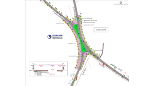
Final Proposal
As per topography of Phase-II area we have identified to two lowest points i.e. L1 and L2 and ridge is in between above points. L1 is located on south west corner and L2 is located on east side of Phase-II area. The effluent of following plots will be collected at L1 location.
Proposal of Effluent collection System – We have studied three options for collection of effluent drainage system.
Various Options of CETP –
Membrane Bioreactor: – The MBR is a suspended growth-activated sludge system that utilizes micro porous membranes for solid / liquid separation. It represents a decisive step forward concerning effluent quality by delivering a hygienically pure effluent and by exhibiting a very high operational reliability. An MBR is a hybrid of a conventional biological treatment system and physical liquid–solid separation using membrane filtration in one system. It helps in removal of TDS (Dissolved Solids). It helps to achieve maximum permeate of desired parameters to be reused in process. The technology focuses on maximum recovery with very less reject of < 5%.
MBBR (Moving Bed Biofilm Reactor): –
Small cylindrical shaped polyethylene carrier is added in aerated or non-aerated basin to support biofilm growth. Biomass grows primarily on protected surface on the inside of the carriers. Air agitation or mixers are used to continuously circulate carriers. Perforated plates at the outlet of the tanks keeps biofilm carrier inside the tank. MBBR can be a single reactor or configured as several reactors-in-series. Carriers occupy 25-70% of tank volume. The specific surface area of carrier is about 500m2/m3. The carriers are slightly buoyant and have a specific gravity between 0.94 and 0.96 g/cm3. Media carrier life is around 15-20 years.
Sequencing Batch Reactor (SBR): –
It is similar to an activated sludge process. The fundamental difference is that this system uses one tank for all the treatment steps, rather than using different equipment for each step in the process. As the term “sequencing” suggests, SBR uses time, rather than space, to accomplish its wastewater treatment purposes. SBR is often part of a broader framework for wastewater treatment. Other stages, such as grit removal, may come before, and some, such as disinfection, can follow. In some cases, SBR alone may work as the sole means of treating wastewater, depending on the quality of the influent and the desired quality of effluent.
Phytoremediation: –
Phyto means plant, and remediare means restoring balance. It is defined as “the efficient use of plants to remove, detoxify or immobilise environmental contaminants in a growth matrix (soil, water or sediments) through the natural biological, chemical or physical activities and processes of the plants”. Plant roots take contaminants from the ground into the “body” of the plant. The plant root zone is referred to as the rhizosphere, this is where the action occurs. This soil supports large populations of diverse microorganisms. This is due to chemicals exuded by plant roots which provide carbon and energy for microbial growth. This combination of plants and microorganisms appears to increase the biodegradation of compounds.
Conclusion and Recommendation –
We have studies three options and the block costs of each option are worked out as elaborated above. In option no 1, 2 Separate ETP are proposed at location L1, L2 and for option no 3 either new ETP or expansion of existing CETP is proposed.